| |||||||||||||||||||||||||||||||||||
| |||||||||||||||||||||||||||||||||||
                        DESIGN AND INSTALLATION OF A

                             WEIGHING LYSIMETER


                  M.D. Sayler, M.D. Allen      December, 1984
                  R.D. Burman, J.L. Smith          WWRC-84-09


                               Final Report
                           (Project No. 2-92384)

                               Submitted to

                       Wyoming Water Research Center

                           University of Wyoming

                             Laramie, Wyoming


                               Submitted by

                      M.D. Sayler, Research Assistant
                           M.D. Alien, Engineer
                          R.D. Burman, Professor
                      J.L. Smith, Professor and Head
                  Department of Agricultural Engineering
                           University of Wyoming
                             Laramie, Wyoming


                               December 1984
DESIGN AND INSTALLATION
of a
WEIGHING LYSIMETER
Efficient planning and use of available water requires accurate evaluation of all components in the water budget. Most water users are legally entitled only to the quantity of water consumptively used which is usually a portion of the total water diverted. This is generally the case in both interstate and intrastate water laws, policies and compacts.
It is obvious that water is essential for food production. This water can come from precipitation or from irrigation which is applied to augment natural rainfall. At the present time, competition for a finite amount of water is increasing. Major competition for water is between agricultural production, municipal uses, industrial uses and recreational uses. In the western United States this situation is aggravated by the rapidly developing energy industry.
Irrigation water requirement estimates are very important for project planning and irrigation scheduling. In addition, consumptive use by crops is the limit of water transferred from agriculture to other uses according to western water right laws. All of these factors have served to increase the importance of estimating irrigation water requirements. In many cases, such as irrigation water right transfers, the economic stakes are enormous; these stakes comprise, first, the sale value of the water involved and, second, the adverse effects of water right transfers on agriculture.
Wyoming water law is consistent with western water rights law in that the following criteria are imposed upon any change in water use. An example of such a change would be from agricultural to municipal uses.
It is physically and financially impossible to measure vegetative water use in every area of interest in the State of Wyoming. Methods and/or models must be developed with which reliable estimates can be made using limited information.
The State of Wyoming also has several on-going projects which are directed towards modeling vegetative water use in given basins. These projects involve measuring vegetative water use with both disturbed and undisturbed non-weighing lysimeters. Lysimeter data are used with environmental and climatic data to calibrate and evaluate proposed vegetative water use models.
The weighing lysimeter represents the best available technology for determining vegetative water use. The research reported herein involved developing and installing a weighing lysimeter in the Laramie River Basin, an area which has been included in Agricultural Engineering water use research for many years. Data will be used to evaluate experimental errors or bias introduced into models through use of less reliable equipment.
The undisturbed weighing lysimeter is a permanent research facility which will contribute to the educational and research programs of the Wyoming Water Research Center and cooperating academic departments. In addition to providing needed research data, it will serve to demonstrate the best available technology for measuring vegetative water use.
The relative sophistication of a weighing lysimeter is such that it requires more attention and greater technical expertise for satisfactory operation than does a non-weighing lysimeter. This could present a serious problem because the time and effort required would be prohibitive if the lysimeter was installed in a remote area.
Fortunately, the Agricultural Engineering Department has installed and maintained lysimeters continuously in the Laramie area for many years. The University, located in a region which produces irrigated meadow hay, is uniquely located for this research. In this area, the weighing lysimeter can be conveniently observed and properly maintained to insure reliable research results. A weighing lysimeter near Laramie is located at the highest elevation of any similar facility in the United States and probably in the world. Models verified under these conditions would be unique. The information obtained should significantly enhance the reliability of vegetative water use models and should thereby enhance the analysis of water use within Wyoming.
The lysimeter facility provides a unique tool for botanists, agronomists and other plant scientists on campus. By recording information such as soil moisture conditions within the lysimeter and plant characteristics such as growth rates and maturation it will be possible to more closely evaluate and model the influences of environment on plant growth.
Accurate plant water use and growth models could help provide the information needed to objectively consider controversial water policies. For example, maintaining in-stream flows for fisheries would cause higher water tables and increase riparian plant growth. The effect of increased water availability from the ground water on increased vegetative growth and water use could be evaluated in the weighing lysimeter.
OBJECTIVES
The purpose of this research was to develop and install an undisturbed weighing lysimeter in the Laramie River Basin. This location will facilitate providing the necessary management to insure continuous and reliable operation.
The lysimeter contains an undisturbed soil profile with accompanying vegetation. To the best knowledge of the authors, the lysimeter is the first system of its type installed anywhere, particularly at high elevations.
Once operational, the lysimeter will be used to:
BACKGROUND INFORMATION
Recent unpublished research by Burman (1983) has indicated that:
Normal lysimeter installation involves excavating soil, placing the tank or lysimeter in the excavation and placing the excavated soil in the lysimeter. The soil profile is disturbed and soil structure is virtually destroyed. Vegetation is seeded or transplanted in the lysimeter. Burman's observations concerning soil disturbance can be alleviated using procedures recently developed for undisturbed lysimeter installation.
If all possible pathways of rainfall disposition are considered, effective rainfall is indeed a very complex concept. In fact, the working definition used will vary with the discipline involved (Dastane, 1974). Effective rainfall means one thing to a hydrologist and a different thing to a scientist involved in irrigation scheduling. In addition, it is easy to misuse the limited procedures available for estimating effective rainfall. In many cases, expediency rather than judgment is the guiding principle.
Dastane (1974) presents a very extensive discussion of effective rainfall. His publication shows that the disposition of rainfall involves direct evaporation from plant surfaces, surface runoff, interception by vegetation, infiltration into soil, and other processes. Weighing lysimeter measurements are the most precise method of determining effective rainfall because all components of the water balance are measured (Dastane, 1974).
Design factors involved in lysimetry were reviewed by Harrold (1966) and Tanner (1967). Soil profile depth and disturbance, siting, soil thermal modifications, wind, and drainage are important considerations.
Two different types of weighing lysimeters have been developed. These involve counterbalancing the dead load (scales approach) of the lysimeter (Black et.al., 1968; Pruitt and Angus, 1960), or using sensitive load measuring devices. (Armijo et.al., 1972; Ritchie and Burnett, 1968). The latter approach is currently more attractive, particularly because of the accuracy, precision and utility of computer controlled data acquisition systems. Often both approaches are combined in weighing lysimeter construction. Modern microprocessor controlled data acquisition systems allow frequent readings (up to 500 or more times per second) and can compute and store thousands of data samples in the desired output format.
LYSIMETER DESIGN
The general concept of a weighing lysimeter requires four major elements. These include the container to hold the soil, water and vegetation; a rigid foundation; the force measuring or weighing system; and the data acquisition and analysis system. Accessory instrumentation is also required to measure and record climatic data.
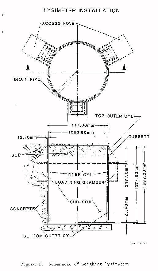
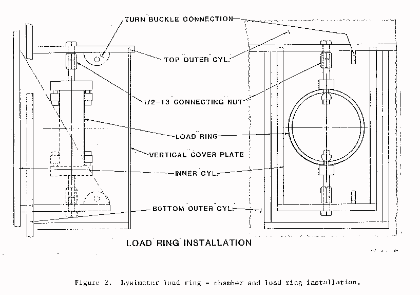
The lysimeter designed and installed in this research is illustrated schematically in Figure 1. It consisted of two cylindrical containers, one of which fitted inside the other. The inner cylinder contained the soil, water and vegetation, and its weight was measured using three strain gage load rings. One of the load rings is illustrated in the schematic shown in Figure 2.
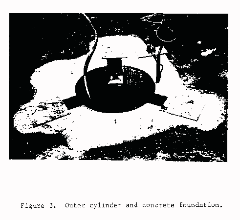
The outer cylinder formed the working surfaces of the foundation and, for ease of assembling the lysimeter, was fabricated in two parts. The lower part was installed in the earth in concrete, as shown in Figures 1 and 3. The inner container was then placed in the cavity, and the upper part of the outer cylinder was installed. Referring to Figure 1, note the flange on the inner cylinder to which the bottom of the load ring was attached. The upper part of the outer cylinder was sealed to the lower part and rested on the concrete foundation and provided the attachment point for the top of the load ring. The inner cylinder was thus suspended within the outer cylinder by the three load rings, which measured tensile forces. After installation was completed, undisturbed soil and vegetation was placed around the outer cylinder to restore the original ground surface elevation and vegetation.
CYLINDER DESIGN
Cylinder dimensions were selected based on maintaining a suitable diameter to depth ratio (greater than one), and the availability of large diameter steel pipe. The inner cylinder used in the lysimeter was 1067mm in outside diameter with a 9.5 mm wail thickness and 1372mm long. A 12.7 mm thick steel plate was welded to the bottom.
The outer cylinder was 1118mm in diameter with a 12.7 mm wall thickness. This provided a radial clearance of 12.7 mm between the inner and outer cylinders. Minimal clearance between the cylinders was desirable from the standpoint of reducing effects of surface disturbance on the lysimeter, but some clearance was necessary to facilitate assembling and aligning the two cylinders. Nominal dimensions and clearances for the cylinders are shown in Figure 1.
LOAD RING ATTACHMENTS
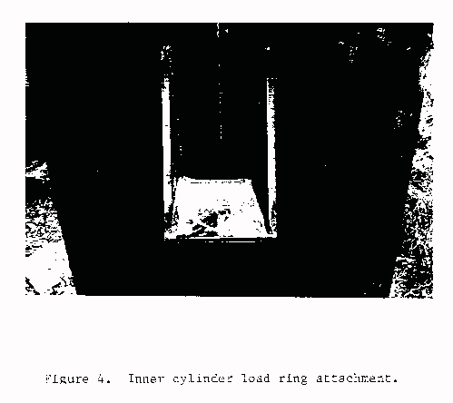
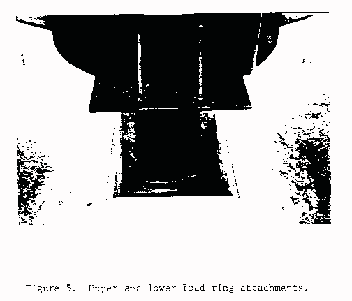
Notches were provided in the foundation at 120� intervals, (see Figure 3) to accommodate the load rings and load ring attachments. The load ring attachment to the inner cylinder is shown in Figure 4, and the upper and lower attachments are shown in Figure 5. Refer also to Figure 2 for details.
The method of attaching the load rings to suspend the inner cylinder inside the outer cylinder is shown in Figure 2. Referring to the figure, notice the turnbuckle connections, which were provided to relieve the force in the load ring. This assembly was necessary to facilitate installation and removal of the load rings in the event of a malfunction. The well rod nut on top of the load ring was used to align and level the inner cylinder within the outer cylinder. A vertical plate was placed over the load ring access area and attached using the bolts visible in Figure 5. Silicon sealant was used as a gasket to prevent water from entering the area around the load ring.
LOAD RING DESIGN
Specifications, design calculations and calibrations of the load rings are given in the Appendix. Each load ring was configured in a full bridge strain gage circuit, using MM-WA-06-250BG-120 strain gages. Lead wires were run from each load ring to the data acquisition system.
LYSIMETER LOCATION
The weighing lysimeter was installed in a native grass hay meadow on the Monolith Ranch, located approximately 12 kilometers southwest of Laramie. The meadow is southeast of the Laramie River, at an elevation of approximately 2300 m.
The specific site was selected based on an investigation of subsurface soil and water conditions, condition of the meadow, terrain and accessibility. It was necessary to locate the lysimeter near the outer edge of the meadow to provide a stable foundation. High groundwater during the irrigation season in lower portions of the meadow would have prevented establishment of a suitable foundation.
A small rise in the terrain exists to the southeast of the lysimeter site, but no appreciable rise occurs for more than 75 m. This should be adequate to avoid surface wind disturbance in the southeast-northwest directions. Prevailing winds at the site are from the southwest and should be unaffected by the topography.
Greasewood and similar brush was cleared from around the site. Regrowth will be cleared in the Spring of 1985 using an appropriate herbicide.
The site was fenced to enclose an (30 m by 30m) area surrounding the lysimeter. The fence was erected using four strands of barbed wire and two tiers of horizontal poles. The fence was necessary to prevent livestock from stepping on and/or grazing on the lysimeter. There remains an unavoidable possibility of damage to the lysimeter from wildlife.
LYSIMETER DRAINS
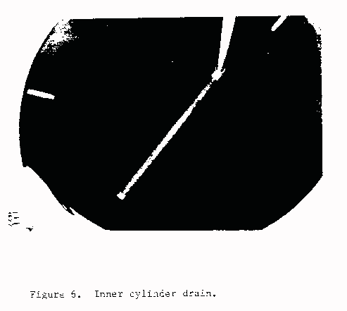
Drains were provided in both the outer and inner cylinders of the lysimeter. The outer cylinder drain (Figure 1) was needed to prevent accumulation of water between the cylinders which could cause the inner cylinder to float. Such a buoyant affect would reduce the apparent weight of the inner cylinder and would cause an incorrect weight reading. Water which accumulated between the cylinders was removed using a small hand operated suction pump.
The drain for the inner cylinder was placed prior to installing the soil and vegetation. This drain consisted of a 50 mm PVC pipe run down along the inside of the vertical wall of the inner cylinder and across the bottom of the cylinder. The drain is shown in Figure 6. The pipe across the bottom was perforated with slits to allow water entry. A filter was formed around the pipe by first placing a screen around the pipe, then sand and finally a shallow layer of fine gravel. Installation of the filter was necessary to prevent transport of fine material from the soil into the drain.
In operation, the drain in the inner cylinder will be used to remove excess deep seepage waters from the lysimeter and/or to control the depth of the water table. Using this drain, it will be possible to simulate any desired water table depth and to control the water table depth accurately.
SOIL AND VEGETATION INSTALLATION
Soil and vegetation were placed in the inner cylinder to duplicate as closely as possible natural conditions surrounding the site. Subsoil in the vicinity was gravelly sandy loam and thus it was not possible to obtain a completely undisturbed soil profile in the lysimeter.
Subsoil was removed from an adjacent pit, and shoveled into the inner cylinder and hand compacted in 15 cm lifts to within approximately 45 cm of the top. This was approximately the same depth as found in the surrounding soil profile. Because of the granular nature of the soil, disturbance should not significantly affect its function in the lysimeter.
The subsurface soil was kept-moist and allowed to settle for a week prior to placing the topsoil and vegetation.
The top 45 cm of topsoil and vegetation was installed undisturbed. The sample was obtained by first digging a trench around a selected area, removing the sample and then carving it by hand to fit the top of the inner cylinder. This procedure provided a relatively undisturbed vegetation sample.
When soil and vegetation installation were completed, the lysimeter area was irrigated for the remainder of the 1984 growing season to facilitate reestablishment and healing of any soil or plant wounds within the lysimeter and the construction area around the lysimeter. This level of attention should provide very representative growing conditions for the 1985 season.
DATA ACQUISITION AND RECORDING
The heart of the lysimeter data acquisition system is a Campbell Scientific CR-7 measurement and Control System (Campbell-Scientific, 1982). This system is solar powered, with battery back-up. It has the capability to sample multiple data channels several times a second, perform various calculations using the data and pre-programmed information, and to store the results in any desired format. The stored data can be unloaded on a tape cassette on a weekly basis, and further analyzed with digital computers. Data sampling intervals can be selected ranging from several times per second to hourly.
In addition to recording and analyzing the lysimeter weight data, the CR-7 was used to record climatic data using the following instrumentation:
Solar Radiation - LI-COR, LI-200S Pyranometer
Precipitation - Sierra Tipping Bucket Raingage - RG 2501
Wind Direction - Met-One, 024A Wind Direction Sensor
Wind Speed - Met-One, 014A Wind Speed Sensor
Temperature and Relative Humidity - Phys-Chem Research, PCRC-11
RH Sensor and Fenwell Electronics
UUT51J1 Thermistor (Model 207)
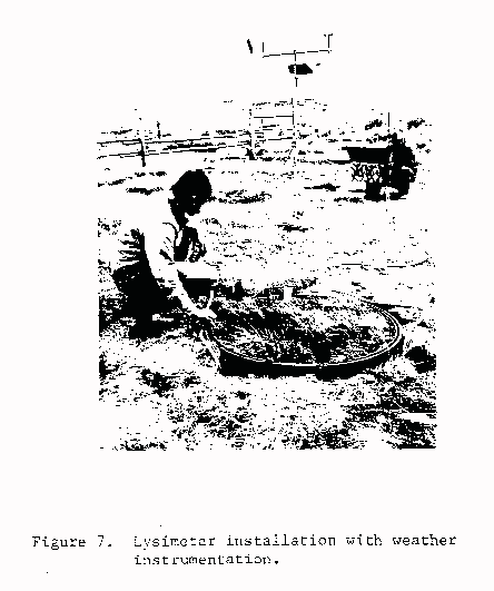
Weather sensors were mounted on a Campbell Scientific CM-lO tripod, located approximately 10 m southeast of the lysimeter. The solar system used to power and charge the CR-7 batteries was a Campbell-Scientific model SX1O photovoltaic power source.
PERFORMANCE and CONCLUSION
The lysimeter was operated during most of the month of September, 1984. All systems were checked for satisfactory operation and minor problems in programming the CR-7 were corrected.
Work on planning, design and installation of the lysimeters began in January, 1984 and was completed in August, 1984. The completed installation is shown in Figure 7. Behavior and performance of the lysimeter observed during September, 1984 provided reasons for an optimistic viewpoint of the future uses of this unique instrument.
REFERENCES CITED
Armijo, J. D., G. A. Twitchell, R. D. Burman, and J. R. Nunn. 1972. A large, undisturbed, weighing lysimeter for grassland studies. TRANSACTIONS of the ASAE 15(5):827-830.
Black, T. A., G. W. Thurtell, and C. B. Tanner. 1968. Hydraulic load-cell lysimeter, construction, calibration, and tests. Soil Sci. Soc. Am. Proc. 32:623-629.
Burman, R. D. (1983). Personal communication.
Dastane, N. G. (1974). Effective Rainfall. Irrig. Drain. Paper 25. 62 pp. FAO, Rome.
Campbell Scientific Inc. 1982. CR7 Operator's Manual. Campbell Scientific, P.O. Box 551, Logan, UT.
Cook, N. H., and Ernest Rabinowicz. 1963. Physical Measurement and Analysis, Chapter 5. Addison-Wesley, NY.
Harrold, L. L. 1966. Measuring evapotranspiration by lysimetry. In: Evapotranspiration and its role in water resources management. Proc. ASAE, St. Joseph, Michigan, p. 28-33.
Pruitt, W. 0. and D. E. Angus. 1960. Large weighing lysimeter for measuring evapotranspiration. TRANSACTIONS of the ASAE 3 (2): 12-15, 18.
Ritchie, J. T. and E. Burnett. 1968. A precision weighing lysimeter for row crop water use studies. Agron. J. 60:545-549.
Tanner, C. B. 1967. Measurement of evapotranspiration. In: Irrigation of Agricultural Lands, R. M. Hagan, H. R. Haise, and T. W. Edminster (eds.) Agron. Monograph 11:534-545.
APPENDIX
DESIGN OF LYSIMETER LOAD RINGS
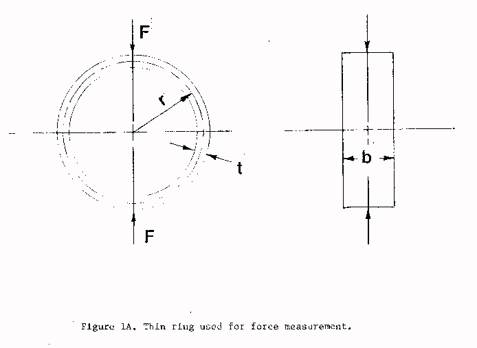
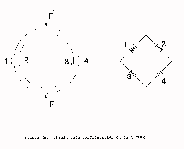
The lysimeter load rings were designed based on the analysis presented by Cook and Rabinowicz (1963). Specifications for the Campbell Scientific CR-7 measurement and control system were given by Campbell Scientific (1982).For a thin ring in compression, the maximum strain due a radial force occurs at 90� with respect to the load. Further, for a tangential load applied at the same point, the 90� position is a strain node; that is, the 90� position has zero strain for the tangential load. Therefore, a thin ring can be instrumented to measure only radial loads by mounting electrical resistance strain gages on the ring at 90� with respect to the point of application of the load. These strain gages will be sensitive only to the radial load.
Consider the thin ring shown in Figure 1A. At 90� with respect to the load F, the strain is given by the equation:
E 90� = 1.09 Fr
Ebt2
Where r, b and t are dimensions defined in Figure 1A, and E is the modulus of
elasticity of the material used to fabricate the ring.
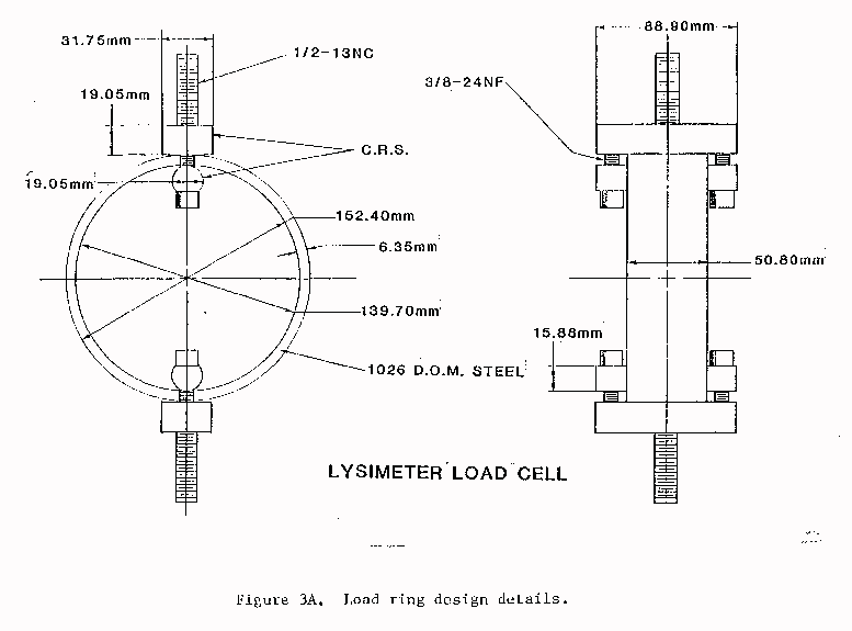
The following dimensions were used for the lysimeter load rings;
                  r = 76.2 mm
                  b = 50.8 mm
                  t =  6.35 mm
The rings were fabricated from steel for which E = 200 GPa, and the yield
point is 517 MPa.
The total weight of the soil and soil container of the lysimeter was assumed to be 33.36 kN, or each of the three rings would support, a nominal maximum load of 11.12 kN. For this load, the strain is 2.25 x 10⁻³, which is equivalent to a stress of 450 MPa.
Note that on the ring, the outside surface is in tension and the inside surface is in compression. Therefore, when four gages are mounted on the ring, two on the outside and two on the inside, the gages can be wired in a four-arm active configuration as shown in Figure 2A.
The output of a four arm active bridge is related to the input voltage by the equation:
                                 v = GF (2)
                                Vo
where v is the output voltage, Vo is the input voltage, GF is the gage factor
(2.08) and � is the strain in one gage.
Assuming elastic behavior and an input voltage of 5 volts, the sensitivity of the ring to changes in load can be calculated from:
                      DF =  v Ebt2
                                Vo (GF) (1.09r)
Using the detection limit of the CR-7, equal to 5 x 10⁻⁶ volts, the load
cell will be sensitive to a change in force of approximately 2.3 Newtons.
This is equivalent to approximately 0.3 mm of water on the surface of the
lysimeter.
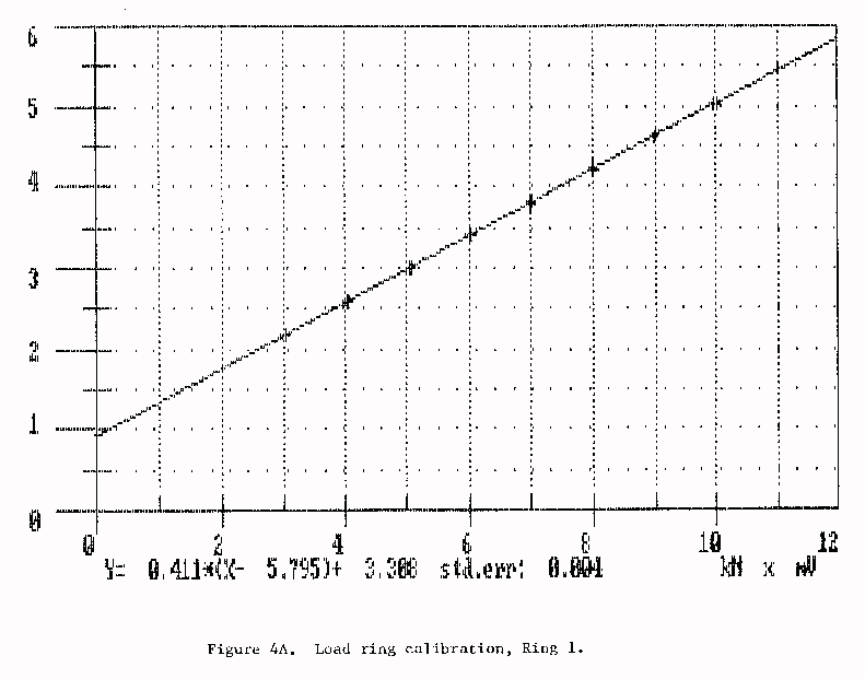
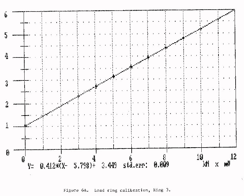
Four identical load rings were fabricated. Design details are shown in Figure 3A. These were calibrated using an Instron Model 1125 testing machine, and exhibited linear load-voltage relationships with the coefficient of regression (r2) essentially equal to 1 in all cases. Calibration data for the load rings are given in Figures 4A through 6A.

Water Resources Publications List
Water Resources Data System Library |
Water Resources Data System Homepage
| |||||||||||||||||||||||||||||||||||